|
SUPPORT SITE |
|
Consider a multi-stage rocket that we want to reach a certain burnout velocity. If we know the structural ratio and exhaust velocity (or Isp) of each stage, what is the best way to distribute mass across the stages? The objective, as always, is to maximize the payload mass. It turns out that if all of the stages have the same structural ratio and exhaust velocity, there is an analytic solution to the problem. If any stage is different, however, the problem can only be solved numerically.
The OptimalPayloadRatio function performs this optimization. It optimizes the overall vehicle payload ratio. In other words, it maximizes the payload mass for a given total takeoff mass. The example shown below is for a 3 stage vehicle where the stage structural ratios are all 0.052, and the Isp values are 315.5, 258.2 and 234.9 seconds. A range of burnout velocities are considered, from 4 to 20 km/s.
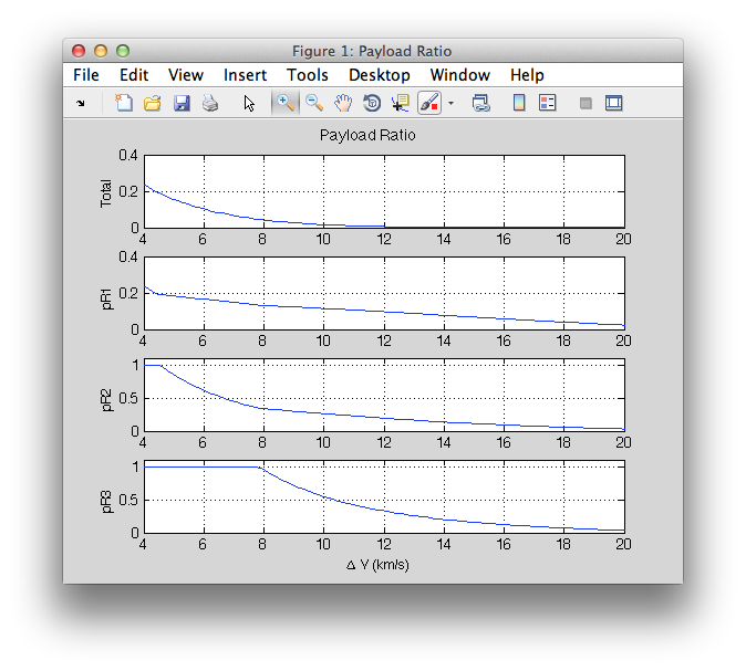
Interpreting this plot shows some interesting results. For burnout velocities below about 8 km/s, the third stage payload ratio is equal to 1. Below 4.5 km/s, the second stage payload ratio also goes to 1. When the payload ratio of a stage goes to 1, it means the mass of that particular stage drops to zero, so it can be removed. This shows that, given our stage properties, a single stage is best up to 4.5 km/s, a two-stage vehicle is best from 4.5 to 8 km/s, and all three stages are best beyond 8.5 km/s. Also, note how quickly the overall payload ratio drops off. It drops to 5% at 7.6 km/s. It takes more and more vehicle to accelerate a given payload to greater velocities.
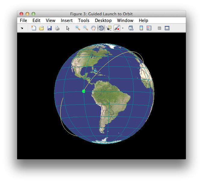
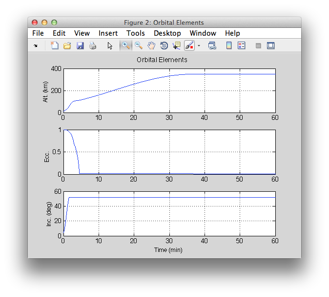
In this example, the dynamics of a multistage launch vehicle is simulated with a guidance method that puts it into low-Earth orbit (LEO). The "example rocket" model is loaded from the RocketDatabase. This is a 4 stage vehicle with a total delta-v capability of 9.17 km/s. The first 3 stages burn consecutively and follow a gravity turn trajectory, where the thrust is aligned with the velocity vector. The fourth stage applies a guidance method directing the thrust to first raise the apogee to a desired altitude, coast to that altitude, and then thrust to circularize the orbit. The built-in demo in the "GuidedLaunch3D" function generates the plots below.
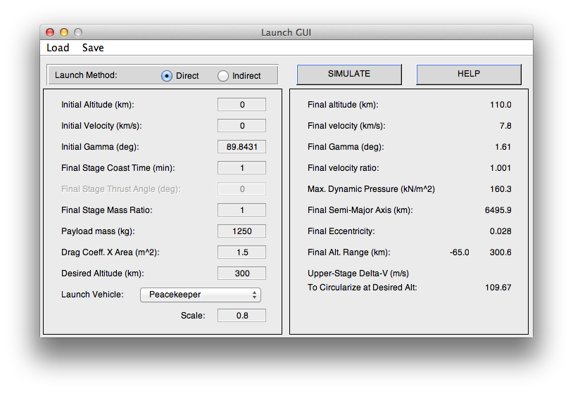
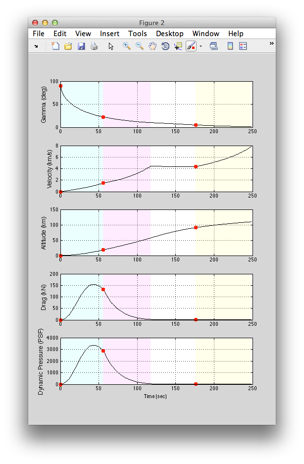
The LaunchGUI in LVT provides a simple UI for designing a direct or indirect ascent to orbit for a multi-stage vehicle. You can first select a vehicle model from the provided database, and scale it to be larger or smaller if you wish. You then set the payload mass and target orbit altitude. Finally, choose a direct or indirect launch. A direct launch has a coast time prior to the last stage, then uses the last stage for apogee raising and orbit insertion. An indirect launch fires all stages consecutively, applying a positive thrust angle to the final stage for apogee raising, then coasts to apogee and applies a burn to circularize. Depending on the method chosen, specify the coast time or thrust angle, and hit the Simulate button. This simulates the boost phase and computes the delta-v required to circularize for orbit insertion at the desired altitude. The stages are shown with different shaded backgrounds in the time history plots to the right.
You can save your settings to a mat file and re-load them later. Example settings are provided in the toolbox to get you started.
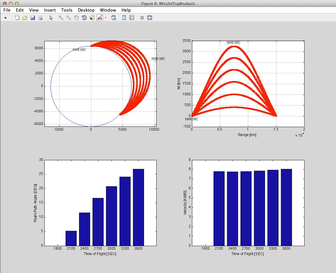
What burnout velocity does a launch vehicle need to reach to fly a sub-orbital arc from one set of geographic coordinates to another? What is the relationship between the velocity, flight path angle, maximum altitude, and flight time for this range? The SubOrbTrajAnalysis function offers a convenient interface for quickly computing and displaying this information. The plot shown below is produced by SubOrbTrajAnalysis for a latitude change of 45 deg and a longitude change of 180 deg, covering a range of 15,000 km.
